Whether you have a CNC press brake or not, there are a few things you should know about its accuracy. Firstly, the X and Y axis determine the accuracy of the bending. The Y axis controls the up and down movement of the top beam, while the X axis is responsible for bending accuracy.
Y Axis Controls The Up And Down Movement of The Top Beam
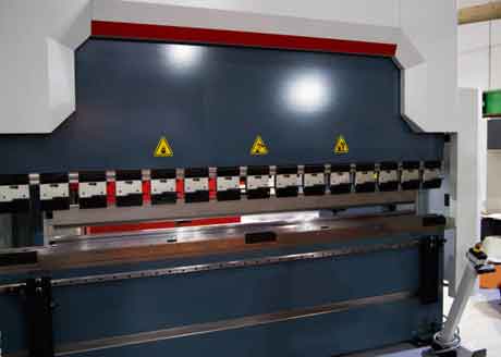
Y axis is one of the axes on a press brake. It is responsible for a variety of tasks, such as positioning the gage fingers. In addition, it controls the speed of the top beam. If you are considering buying a press brake, it is important to understand the Y axis.
The Y axis is the smallest of the four axes in the press brake. It has the capacity to control the UP/DOWN of the ram and the angle of the part being formed. In addition, the Y axis is controlled independently for a complete level of control.
The Y axis is also responsible for moving the back gauge up and down. It also controls the jogging axis. It can also be used to select the “3” stops at the material surface.
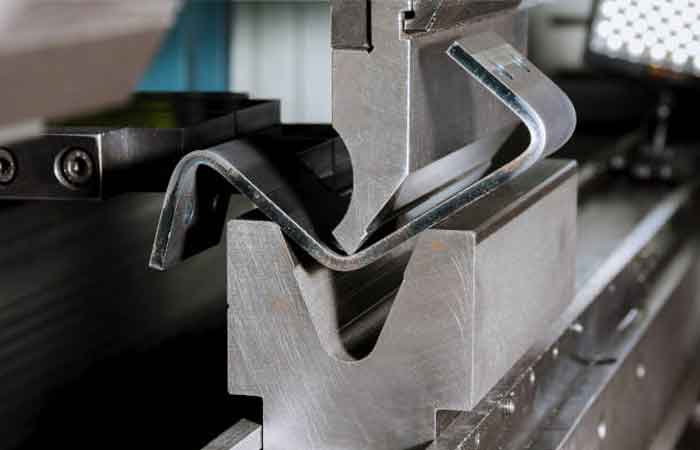
X axis determines the bending accuracy of the workpiece
X axis is one of the important axes in CNC press brake. It determines the bending accuracy of a CNC press brake. X axis can be divided into X1 and X2 axes. In the X2 axis, the back gauge is tilted to create an angled bend line in relation to the back of the work piece.
X axis also determines the length of the flange of the workpiece. In addition, the stop finger of the back gauge can move independently. The X axis positions the stop finger closer to the bending tools. When the sheet metal enters the back gauge, the stop finger accurately positions the plate.
The Y axis controls the up/down movement of the ram. It also controls the height of the opening of the ram. It also controls the depth of the bend.
Hydraulic crowning system
Having a hydraulic crowning system for your CNC press brake is a good way to improve bending accuracy. It can compensate for deformities that occur during bending. It is also a good way to improve the accuracy of small batch workpieces.
The system is generally installed before a machine is purchased. The system can be retrofitted to an existing press brake. Some press brake manufacturers offer tables that can be retrofitted to include a crowning system.
Crowning is used to offset the deflection of the press brake’s table and ram. It also provides an equal force between the tooling and the workpiece. Crowning has been in use since the 1970s, and is especially useful on press brakes that have long beams.
The compensation system, or crowning system, is a motorized axis that uses a pressure feedback signal from the upper hydraulic ram cylinders to calculate the effort required to produce the same bottom-dead center position as the actual workpiece. Crowning is useful for high-strength bending, especially on press brakes with long beams.
Wedge-style crowning system
Deflection in press brakes is a well known problem. Deflection affects the angle of bend and affects the bending accuracy of the sheet material. Crowning is an effective method to compensate for this deflection. It is generally used on press brakes that have 80-ton capacity or higher.
Crowning systems can be purchased from press brake manufacturers. They can also be retrofitted to existing machines. Crowning systems are designed to minimize scrap and increase bending accuracy. Crowning is also helpful in bending parts that are longer than 40-60 inches.
Crowning systems can be categorized into two different types: mechanical and hydraulic. The mechanical crowning system uses multiple groups of wedge blocks. It is also a simpler system. It is environmentally friendly and does not leak oil. It also has a low failure rate.
Single axis back gauge
Adding back gauge axes to a CNC press brake can increase its productivity. These axes can be used to position a work piece, or they can be used to determine the accuracy of the flange being formed.
In addition to the standard R axis, back gauge axes can also include the Z axis. This axis can help to determine the location of the flange, the level of the top beam, and the motion of the back gauges. The Z axis can also be used to determine the positioning of the back gauges, which can provide uniform support for longer bending sheet metal.
Summary:
Adding the Z axis can also help to increase the accuracy of the flange, the level of a beam, and the motion of the back gauges. It can also be used to position a back gauge to the left or right of the bending tools, depending on the angle being formed.